
That same 6dB attenuator coyld be measured to have a 6db loss at 100khz and a 7dB loss at 1ghz, etc. The purpose here is pretty basic, for example: a 6dB attenuator ideally has a factor of 2 response, I could just multiply my measured voltages by 2 and move on.īut naturally nothing is perfect. The basis for my objective is to convert an discreet time domain signal into the frequency domain with an FFT, fold S-parameter info from a network analyzer into the FFT data, then IFFT the new corrected data back to the time domain. I am looking for methodology on how to correct data for losses present in RF signal paths. The use of external hardware to stop or start the timer is discussed in Chapter 11 when interrupts are discussed.John Asks: Correcting signals for cable and device losses all we need are the instructions “SETB TRx” and “CLR TRx”.

In using software to start and stop the timer where GATE = 0.

However, to avoid further confusion for now, we will make GATE = 0, meaning that no external hardware is needed to start and stop the timers. The hardware way of starting and stopping the timer by an external source is achieved by making GATE = 1 in the TMOD register.

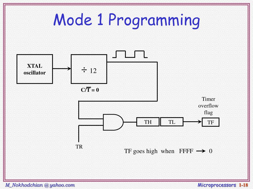
These instructions start and stop the timers as long as GATE = 0 in the TMOD register. The SETB instruction starts it, and it is stopped by the CLR instruction. This is achieved by the instructions “SETB TR1″ and “CLR TR1″ for Timer 1, and “SETB TRO” and “CLR TRO” for Timer 0. The start and stop of the timer are controlled by way of software by the TR (timer start) bits TRO and TR1. Some timers do this by software, some by hardware, and some have both software and hardware controls. What is its purpose? Every timer has a means of starting and stopping. Notice in the TMOD register of Figure 9-3 that both Timers 0 and 1 have the GATE bit. The other bit of the TMOD register is the GATE bit.


 0 kommentar(er)
